The acoustics of Reinhall piles
This week PBS News Hour broadcast a segment about underwater noise, and local efforts in the Pacific Northwest to mitigate the noise from pile driving.  Driven by the release this month of NOAA’s Ocean Noise Strategy Roadmap, the 7.5-minute segment did a decent job of introducing key ocean noise sources (sonar, seismic, vessels).  Marla Holt (NOAA/NWFSC) was interviewed and mentioned amplitude compensation of killer whales in boat noise, though the program juxtaposed ships in such a way that the public might be mislead into thinking our +1dB/dB observed compensation in the S1 call amplitude in the presence of boat noise would also be observed in the presence of ship noise.
The last part of the interviewer’s efforts went to understanding an emerging mitigation technology: Reinhall piles.  She got Per Reinhall, head of the University of Washington Mechanical Engineering Department, to describe a technology he and his grad student helped develop that is being commercialized by a Seattle-based start-up: Marine Construction Technologies.
The company’s web-site has some enlightening diagrams that complement Per’s on-screen description which he helpfully facilitated with a black hand-held model.  Basically, a Reinhall pile is a standard hollow pile that is driven into the seafloor via a mandrel, or central pile of smaller diameter.  The mandrel is fitted with a proprietary shoe and transmits the pressure pulse from the driver via a “very, very stiff spring” into the base of the (outer) pile.  Once in place, the mandrel is removed and can be re-used to drive the next pile.
This innovation reduces sound propagation from the pile to the surrounding seawater by creating an air-filled void between the driven mandrel and the outer pile.  Since air is compressible (unlike seawater), much less of the energy from the driver’s strike propagates to the seawater because it must travel through the air-filled void as well as the (outer) pile wall.  This use of air to absorb some of the pressure pulse from the strike takes advantage of the same physics as bubble curtains — cylindrical clouds of bubbles that rise from rings placed around a pile while it is being driven.
The “secret sauce” of the invention, however says Per, is the shoe at the base of the mandrel. Â It transmits the pressure pulse from the mandrel to the outer pile in a way that reduces the energy transmitted into the seabed. Â The videos on the company web site provide a few hints into how it works.
At 10:07 this (silent, time-lapse) video of in-situ tests done in collaboration with the Port of Tacoma and sponsored by the Washington Department of Transportation shows a glimpse of the shoe as the mandrel is removed from the driven pile.
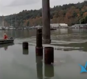
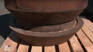
Full-scale mandrel being removed from a driven pile. Note the shoe at the base of the mandrel.
In this video at 2:37, grad student Tim Dardis provides another perspective on the lower end of the mandrel and the shoe as he creates a sub-scale model.
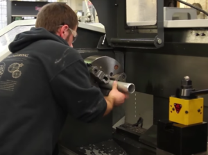
Inserting a sub-scale pile into the lathe. Not sure if this is an outer pile, or an inner pile that is welded to the shoe to create the mandrel. Based on the diameter, I’m guessing inner.
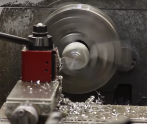
The sub-scale shoe being turned on the lathe. It looks like they are creating a conical surface that will parallel the conical tip of a standard pile.
The mystery in the exciting story is “where’s the spring?”  Per says it is a “flexible coupling” at the bottom of the mandel.  In the lathe video, Tim mentions that the shoe is welded on to the inner pile.  The PBS footage includes short clips of a couple piles on the (Tacoma testing?) dock, as well as a prototype that represents the best public estimate of how the coupling, or shoe, is engineered.
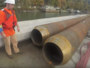
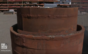
Full-scale piles on the dock. Is the left one the inner pile (mandrel) and the right a standard pile?
Base of a prototype of the Reinhall pile. Â Where’s the spring?
Top of a prototype of the Reinhall pile.
It’s not clear to me where the spring is in this invention. Â But the physics of springs does suggest that the basic idea is a good one (at least for nearby fish, but maybe not for actually overcoming the resistance of seafloor sediments to an inserted vertical pipe).
When a rod-spring system is hit on the top of the rod by an instantaneous force, what happens?  The impact on the end of the rod generates a compression wave that propagates down the rod and eventually compresses the spring a distance which is proportional to a spring constant.  Along the way, energy is transmitted to the adjacent air and through the spring to the sediment.
The dynamics of compressing the spring seem likely to reduce the peak-to-peak amplitude of the compression wave (and pursuant Mach waves in the water and sediment), but isn’t that maximum compression also important in driving the piling through the sediments (which are resisting the driving through friction)? Â Perhaps the acoustic reductions outweigh any loss of efficiency in the driving process? Â One should be careful to not increase sound exposure levels inadvertently — by reducing the noise level but increasing the number of strikes required to drive the pile to the desired depth…
So, how exactly is it put together?  The patent for “Pile to minimize noise transmission and method of pile driving” provide some answers.  First, it suggests that there may be some compliant material used between the inner and outer piles to keep them aligned — at least near the top, and possibly throughout the air-filled void (especially if there are leaks and it fills with water!).
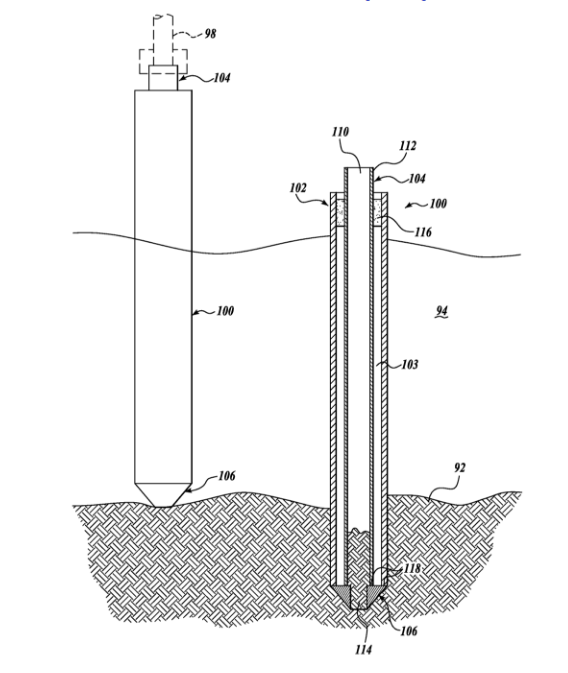
Overview diagram from the schematic. Compliant material (116) helps pile alignment at the top. The driving shoe (106) at the bottom has: an outer diameter equal to or greater than the outer pile’s outer diameter; and, a central aperture (114) to admit sediment with a diameter slightly below the inner diameter of the inner pile.
That all makes sense, but where is the “very, very stiff spring” that’s modifying this massive compression of the inner pile as it reaches the “flexible coupling” at the bottom? Â I thought for sure Fig. 5 of the patent would include a spring…
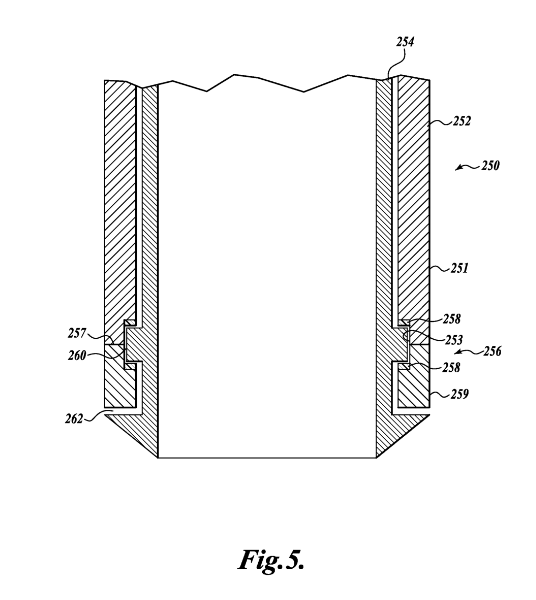
Patent diagram of the inner and outer pile and shoe. Note the flange which connects the inner and outer pile. It pulls the outer pile down behind the shoe as the inner pile is driven. Â I thought 258 would be springs, but no — the patent says “One or two low-friction members 258 (two shown), for example nylon washers, may optionally be provided.”
Still no springs! Â And now the outer pile is welded up so as to “capture” the inner pile. Â I thought the inner pile was going to be re-usable, but now its flange is stuck inside the recess of the outer pile! Â We have, however, got some interesting gaps (260 and 262) separating the inner and outer piles… Â Are we trying to keep water from leaking in?
Maybe, but I don’t get why it’s better acoustically to pull the outer pile down via a flange rather than the aforementioned shoe. Â Maybe the compressional wave transmits less energy to the sediment if it is partially reflected by the flange/recess interface?! Â To me it doesn’t seem worth losing the re-use of the mandrel.
Finally, in the last schematic of the patent (Fig. 6, below) co-inventors Per and Peter (Dahl) of the Applied Physics Lab mention an “elastic connector 285 connecting the inner tube and outer tube” — possibly a spring! Â They suggest it may be “an annular linear elastic spring member with an inner edge fixed to the inner tube 284, and an outer edge fixed to the outer tube 282.”
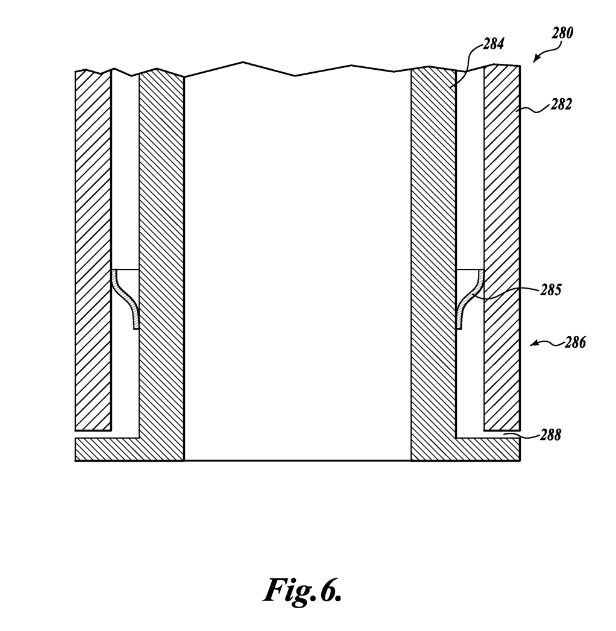
At last a spring! Â 285 is an “annular linear elastic spring member.”
Of course this drawing is a little confusing. Â How are you going to get the inner pile out? Â It seems this also is a non-reusable mandrel “embodiment” of the design. Â And what is 288? Â Mysteriously, it’s not defined in the patent!
No matter how exactly it works mechanically, the invention is effective acoustically.  Overall, the underwater noise is reduced about 20 dB lower (peak-to-peak, or RMS) with the Reinhall pile compared to received levels from a standard pile.  Per explains in the PBS piece that this is equivalent to a 90% reduction in volume (pressure amplitude).  A 20 dB reduction also means the noise is 100 times less intense.
Accolades to the UW and Marine Construction Technology for providing the public with a nice audio clip allowing comparison of the received sound from the control and the Reinhall pile. Â Have a listen!
I’m left wondering who reviews and approves these pretty nebulous patents. Â It seems the design challenge is to optimize acoustic mitigation with efficient installation of the pile — and ideally a pretty standard pile (to save costs and installation steps).
The real innovation of Per and Peter is that they found a way to extend that cylinder of sound-absorbing air down into the sea — not only to the seafloor to block propagation directly in the water (per their ASA talk “Attenuation of pile driving noise using a double walled sound shield”), but also within the seafloor, thereby reducing transmission from the walls of the inner pile to the sediment.  Some of their thought process is captured in this article.
To leverage their good idea within the design constraints I assume, here’s my suggested embodiment:
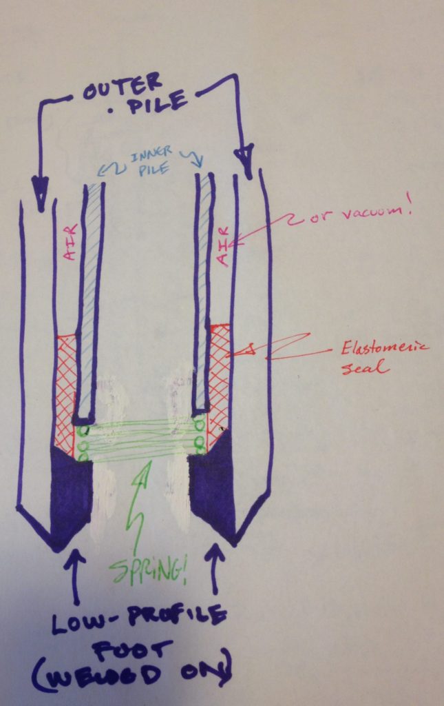
It actually has a big, stiff spring! And:
- minimizes the preparation of the outer pile — just weld to the inner wall of a standard hollow pile a single annular shoe (solid purple) with bevel to guide placement of the inner pile on a driving surface
- seals the connection between the inner and outer pile (to ensure water does not displace the air)Â with an elastomeric material (red) that has a beveled lower edge that weds to the shoe’s bevel.
- Â welds a spring (green) to the base of the inner pile which rests on the driving surface of the outer pile


 Twitter
 LinkedIn
 Facebook